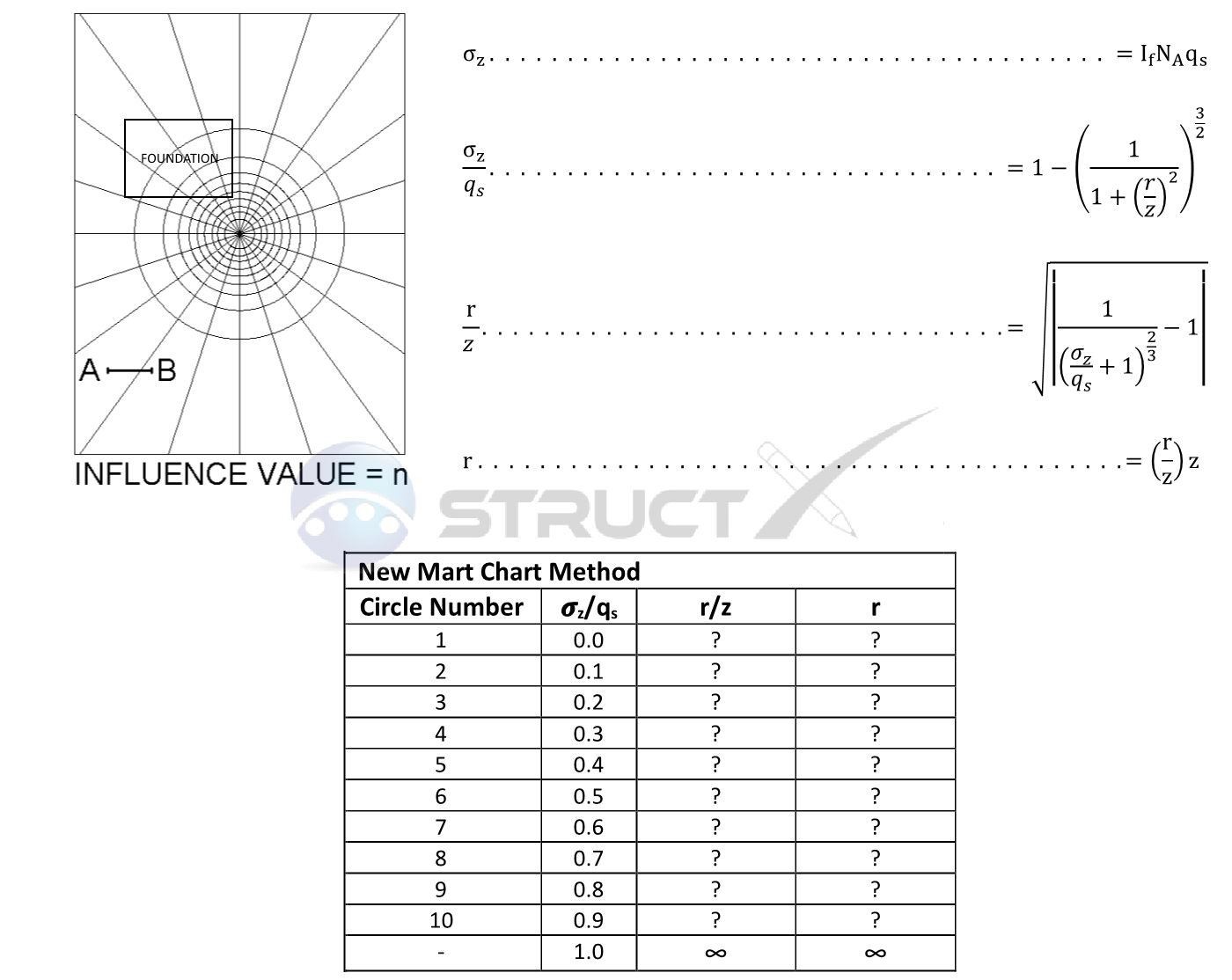
Newmart Chart Method - Foundation of any shape
Any shape of Foundation
Unfortunately, foundations do not always come with convenient to Analyse square, rectangular and circular bearing surfaces with many foundations exhibiting a combination of two, three or even more shapes. Because foundations can come in many different shapes the Newmart chart method was developed. The stress acting on a point of interest as a result of the stress distribution of any shape of foundation can be approximated by drawing the foundation under consideration on a scaled Newmart chart. The procedure for constructing a Newmart chart is as follows:
- Step 1: Prepare a table similar to the one shown below and populate the missing values using the formulas provided.
- Step 2: Construct the chart using circles of radius r, and divide the circles with rays (typically 20 rays, making a total of 200 segments). Draw the scale A-B on the chart for reference which is equal to z. The influence factor IF is equal to 1/segments or 1/200 = 0.005 typically
- Step 3: Draw the loaded area under consideration to the same scale shown on the chart (A-B is equal to z) with the point of interest being the centre of the circles. If the point of interest in below the centre of the loaded area then draw it so it is over the centre of the circles; If the point of interest is below the corner of the loaded area then draw it so the corner of the loaded area is on the centre of circles etc.
- Step 4: With the loaded area now drawn to scale and shown at the correct position from the point of interest, count the number of segments within the boundary of the loaded area - this is the value NA. Because it is likely that there will be numerous partial segments of different sizes, care will need to be taken to ensure the number of equivalent full segments are identified. It should also be remembered that the segments are counted independent of size and that when determining the overall number, half of a small segment plus half of a larger outer segment is equal to one full segment.
- Step 5: Calculate the stress acting on the point of interest σZ using the provided formula below.

Notation and Units
Metric and Imperial Units
The above formulas may be used with both imperial and metric units. As with all calculations care must be taken to keep consistent units throughout with examples of units which should be adopted listed below:
Notation
- σZ = stress increase at point of interest, kip/ft2 or kPa
- IF = influence value based the number of circles and number of rays (typically 0.005)
- NA = number of elements enclosed by the boundary of the loaded area
- qs = pressure on the loaded area, kip/ft2 or kPa
- r = radius of the circle under consideration, ft or m
- z = depth to the point of interest below the loaded area, ft or m
